PLATONIC SOLIDS: A 3D TEXTBOOK
EXHIBIT AT 2015 BRIDGES BALTIMORE
Preface
The richness of ideas found in the Platonic solids gives a wonderful example of the beauty to be found in mathematical thought. A geometry textbook typically develops the ideas with text and two-dimensional drawings. However, three-dimensional geometry is most effectively presented in three dimensions. So, this “textbook” gives a systematic development of geometric ideas, but does so through a series of more than thirty 3D sculptures with explanatory signs. The beauty of the sculptures gives a fitting expression to the beauty of the mathematical ideas – a bridge between sculpture and mathematics. It is hoped that the exhibit will encourage others to use the Platonic solids as a way to introduce in a very concrete way some abstract mathematical concepts, and perhaps it will also encourage others to create 3D textbooks for other topics in mathematics. (The 3D Textbook exhibited at the 2015 Bridges Math-Art conference in Baltimore had actual 3D geometric sculptures, but this website of course can only provide photos of those sculptures.)
The intended audience for the exhibit is anyone who has studied a little high school algebra and geometry, but someone with no mathematical background should find it quite accessible, while those with a sophisticated mathematical background will likely find here some delightful surprises.
Mathematics is an art form. It is an art form in which the medium is pure thought. It is unlike other art forms in that other forms find their expression in physical material. Perhaps we should describe Bridges as an organization dedicated to making connections between mathematics and other arts. In any case, we should not be surprised that we so readily find many connections between mathematics and other arts. Art stimulates inner activity. The sculptures in this collection do so by calling upon the viewer to inwardly form images and visualize forms in movement, to see in the mind what is suggested by, but is not physically present in, the pieces.
There is a multitude of dynamic movement both within each sculpture and between the sculptures. That interaction with the viewer engages one in the choreography of these movements.
Viewing Suggestions
The viewer will find it interesting to look at the shadows cast by the pieces. Also, if one moves about, viewing the pieces from different perspectives, various lines and points will suddenly line up, giving quite stunning views; try this especially with one eye closed.
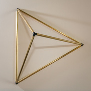
Figure 1a. Tetrahedron, brass, 12x12x12 cm
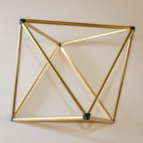
Figure 1b. Octahedron, brass, 12x12x12 cm
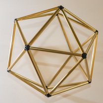
Figure 1d. Icosahedron, brass, 12x12x12 cm
|
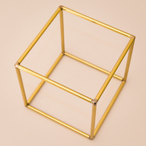
Figure 1c. cube, brass, 12x12x12 cm
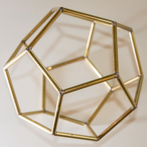
Figure 1e. Dodecahedron, brass, 12x12x12 cm
|
1. Introduction: The Convex Regular Polyhedra Also Known as the Platonic Solids
Basic Definitions
Figure 1 above shows the five Platonic solids. They are very special examples of what are called polyhedra. Looking at a few examples, one readily grasps the concept of a polyhedron, but to express the concept precisely actually requires some care. In fact, in a fictional dialogue, Imre Lakatos sketches the historical development and refinement of the concept of a polyhedron. [Proofs and Refutations, Imre Lakatos, Cambridge University Press, 1981.] The discovery of counterexamples to a theorem of Euler required the refinements. For our purposes, however, we will say that a polygon is a plane figure made up of line segments, called edges, that join consecutive pairs of points, called vertices. It is called regular if all of the edges have the same length and all of the angles are equal to one another. A polyhedron is a figure in space made up of a connected set of plane polygons, called faces, with every edge of each face belonging also to just one other face. A polyhedron is called regular if all of its faces are regular polygons, the faces all have the same number of edges, and the vertices all have the same number of edges. If the faces of a regular polyhedron do not cross one another, then the polyhedron forms a closed surface with an inside and an outside, and it is moreover convex, which means that any line segment, with endpoints inside the polyhedron, lies entirely inside it, i.e. there are no indentations in the surface. The convex regular polyhedra are called the Platonic solids. Plato discussed their symbolic significance in the Timaeus. This textbook will explore the geometric relationships between these five forms.
There Are Exactly Five Platonic Solids
For any convex polyhedron, the faces that meet at a vertex must have angles at that vertex which sum to less than 360°. Regular polyhedra have faces that are regular polygons. Consider the possibilities: Since regular triangles, i.e., equilateral triangles, have 60° angles, one can fit at most five of them at a vertex. Using three, four, or five triangles at each vertex gives rise to the tetrahedron, octahedron, and icosahedron, respectively, shown in Figure 1. Squares with 90° at each angle and regular pentagons with 108° at each angle, can be fit three to a vertex, but no more, since there must be less than 360°. This gives rise to the cube and the dodecahedron, shown in Figure 1. For regular polygons of more than five sides, the angle is at least 120°, making it impossible to fit even three to a vertex. Therefore, we have proved that these five are the only possible convex regular polyhedra.
However, we have to be a little careful here. We have not yet proved that these five actually exist. With brass models right in front of us, don’t we see that they exist? Actually not. When we ask if a regular dodecahedron exists, we mean a perfect one, in which all angles are exactly equal and so forth. Perhaps when we try to put three perfect regular pentagons at every vertex and close up the surface, there will always be some gap or overlap. Physical models are approximations to ideal geometric objects and are never perfect; they cannot answer our question. If a perfect regular dodecahedron exists, it does so in the realm of thought, and hence we can only determine its existence through thinking, that is, through a proof. The proof that the five Platonic solids exist was given already in Euclid’s Elements. We will provide one in the Appendix.
Counting the Number of Vertices, Edges, and Faces
The chart below shows for each of the Platonic solids the number of edges on each vertex, the number of edges on each face, and the total number of vertices, faces and edges.
Exercise 1: For each of the Platonic solids count up the numbers for yourself and see if your count matches the chart.
|
tetrahedron |
octahedron |
cube |
icosahedron |
dodecahedron |
v = edges per vertex |
3 |
4 |
3 |
5 |
3 |
f = edges per face |
3 |
3 |
4 |
3 |
5 |
V = total no vertices |
4 |
6 |
8 |
12 |
20 |
F = total no faces |
4 |
8 |
6 |
20 |
12 |
E = total no edges |
6 |
12 |
12 |
30 |
30 |
Explore the patterns in this chart of numbers. There are many interesting ones. In particular, notice that the cube and octahedron have all the same numbers, but with faces and vertices interchanged. The cube has 3 edges per vertex and 4 per face while the octahedron has 4 edges per vertex and 3 per face. Likewise V and F are interchanged. The total number of edges is 12 for both. We say that the cube and octahedron are dual to one another. Likewise, the dodecahedron and icosahedron are dual to one another; the numbers for faces and vertices interchange.
Question 1: How can we better understand why this duality arises? Is there a geometric image that makes it clear? Why, for instance, do the cube and octahedron have the same number of edges? In the next two sections we will see that these questions can be best answered in the context of what is called “projective geometry”.
Question 1: How can we better understand why this duality arises? Is there a geometric image that makes it clear? Why, for instance, do the cube and octahedron have the same number of edges? In the next two sections we will see that these questions can be best answered in the context of what is called “projective geometry”.
2. Some Projective Geometry
The Infinitely Distant
The geometry of Euclid is concerned with the measurement of length and angle. Projection, as in the casting of a shadow by a point of light, or in perspective drawing, or in a pinhole camera, does not preserve length or angle. However, some geometric properties are preserved by such projections. The shadow of a square may no longer have equal sides or right angles, but it will still be a quadrilateral with four straight-line sides. The shadow of a circle will no longer be a circle, but it will still be a conic section. Projective geometry is the study of the properties of a figure that are preserved by projections.
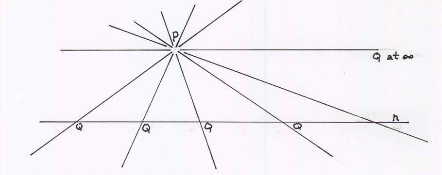
Figure 2a
In Figure 2a, line m rotates about point P; Q, its point of intersection with line n, moves along line n. There is one position at which Euclidean geometry would say that the lines are parallel and that there is no point of intersection, Q. However, projections may send finite points to infinitely distant points and vice versa. A perspective drawing of straight railroad tracks correctly shows the two rails meeting at a point infinitely far away on the horizon. So, projective geometry needs to include the infinitely distant points. At the position in which Euclid would have called the lines parallel, projective geometry says that the two lines still meet at the one point Q, which just happens to be infinitely far away. Looking far enough away, either to the right or the left, one sees the same point, Q, from its two different sides.
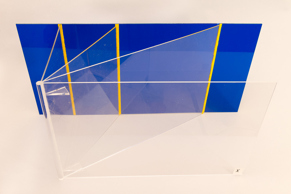
Figure 2b. Acrylic
In Figure 2b, the clear plastic plane intersects the blue plane in a line, shown in yellow. As the clear plane gets closer to the plane marked ‘X’, its line of intersection with the blue plane, i.e., the yellow line, moves further away. Then when the clear plane becomes the plane X, Euclidean geometry says that it is parallel to the blue plane and the two do not intersect, but in projective geometry we say that the two planes still have a line of intersection that just happens to be infinitely far away. Any line has one infinitely distant point, any plane has one infinitely distant line, and the whole of space has one infinitely distant plane.
Visualization 1: Imagine the plane of the floor and the plane of the ceiling of the room continuing out indefinitely far. They intersect on a line, which is the horizon. That line of intersection goes all around you, but it is a straight line; it is not a circle. A circle would intersect a straight line in two points, whereas the horizon intersects a line on the floor in just one point, its one infinitely distant point. The plane of the floor has one infinitely distant straight line on it.
Duality
Because of the inclusion of the infinitely distant, there is a principal of duality in projective geometry, a duality that is lacking in Euclidean geometry. Any two points have a common line, and any two planes have a common line. Interchanging the words, “point” and “plane” converts any true statement into another true statement. For example, any three points, not lying on a line, have a unique common plane (true in both geometries); dually any three planes, not lying on a line, have a unique common point (false in Euclidean, but true in projective geometry).
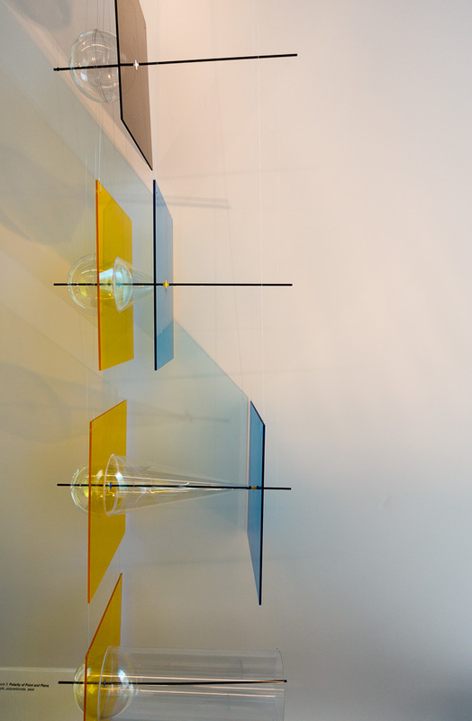
Figures 3a, 3b, 3c, and 3d, from top to bottom, acrylic
3. Polarity in Projective Geometry
The principle of duality interchanges the words “point” and “plane” in any general statement, but it doesn’t associate to a point any particular plane. That’s done by what is called a “polarity”. A polarity pairs each point in space to a plane in such a way that incidence is preserved; if a point lies on a plane, the polar plane and point lie on each other. It follows that as a point moves along a line, the polar plane must rotate around another line; thus each line has a polar line. Figure 3a, b, c, d, depicts a particular polarity, which is defined in terms of some chosen sphere. In Figure 3c (third one down from the top), on the blue sheet is a yellow point, and on the yellow sheet there is a blue point (it may look a bit green). This polarity pairs the yellow point with the yellow plane and the blue point with the blue plane. However, these points and planes are not chosen arbitrarily. Beginning with the yellow point, call it Y, one draws all the tangent lines from Y to the sphere. These lines form a cone, shown in clear plastic. The points where the tangent lines touch the sphere form a circle on the surface of the sphere, (which is also where the cone is tangent to the sphere). This circle lies on a plane, shown as a yellow plastic sheet. This is how the plane polar to Y is found. Moreover, the blue point is where the radius line to Y cuts the yellow plane, and the blue plane is the one perpendicular to the radius line at Y. The blue and yellow points are called conjugate to one another; each lies on the plane polar to the other.
Now try to imagine what will happen as point Y moves closer to the center of the sphere. What happens to the shape of the cone? What happens to the yellow plane? Figure 3b (second from the top) shows us. The yellow plane moves out from the center of the sphere and closer to the yellow point. Imagine now what happens as Y moves still closer and is right on the sphere. Figure 3a (at the top) shows that the yellow and blue points now coincide on the surface of the sphere (and are shown as white), and the yellow and blue planes now become one plane (shown in gray) that is tangent to the sphere at the white point. It is now conjugate to itself.
Now reverse the movement. Follow the movement back from Figure 3a to 3b to 3c. What happens when that movement continues? Imagine the yellow point moving very far to the right. Then the cone will become closer to a cylinder and the yellow plane closer to the center of the sphere. Finally, when the yellow point is infinitely far away, its polar yellow plane will pass through the center of the sphere, the blue point becomes the center of the sphere. What happens to the blue plane? It has become the plane at ∞. Thus, we see that infinitely distant points are polar to planes through the center of the sphere, and the whole infinitely distant plane is polar to the center point of the sphere.
In the Appendix, homogeneous coordinates will be explained and will be used to prove that this construction does indeed give a polarity, i.e., it preserves incidence – if a point lies on a plane, then the polar plane lies on the polar point.
In summary:
The polar of a point is a plane.
The polar of a plane is a point.
The polar of a line is another line.
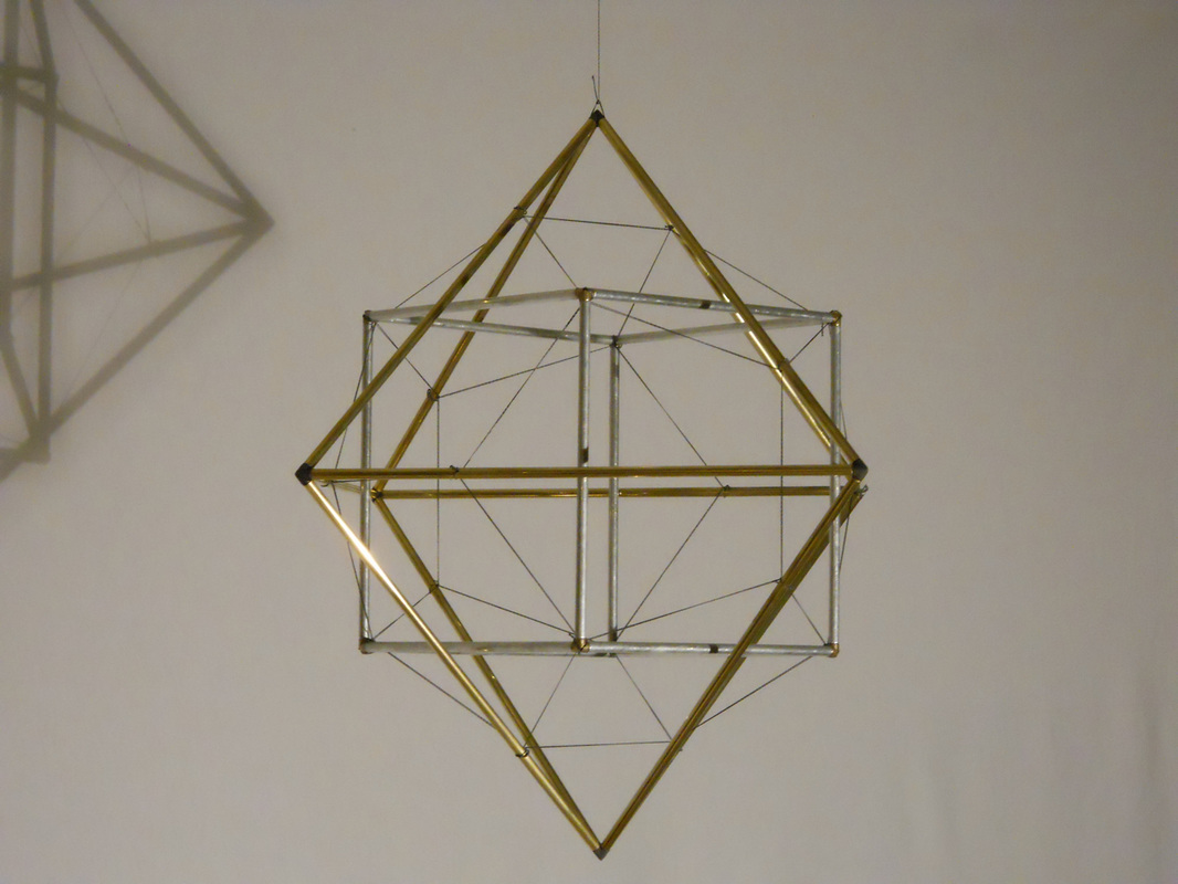
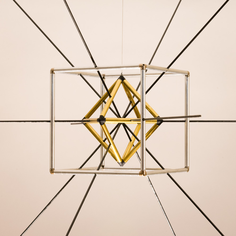
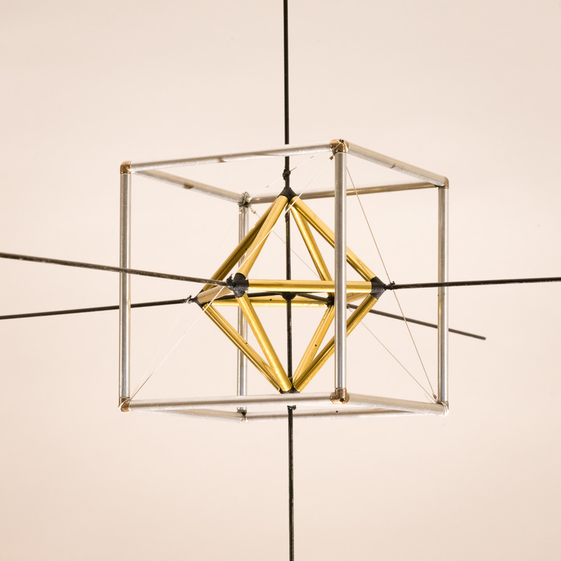
Figure 4a. Polarity of Cube and Octahedron, brass & aluminum, 26x26x26 cm
|
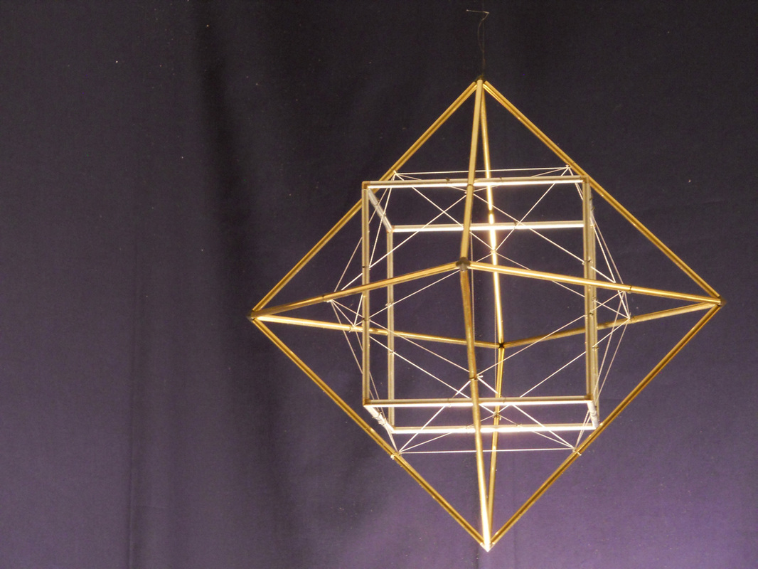
Figure 4b Polarity of Cube and Octahedron, brass & aluminum, 26x26x26 cm
|

4. Polarity of the Cube and Octahedron
Figures 4a and 4b show the same cube (aluminum) and octahedron (brass), but suspended differently from one another. They both show that the cube and octahedron are polar to one another. There is a sphere in between the two. (It is not shown; you have to imagine it.) Relative to that sphere, each face of the cube has a polar point (as in Figure 3); it is just the vertex of the octahedron that is right above it. Likewise each vertex of the cube has a polar plane, which is just the octahedron face right below it. Also, each edge of the cube has a line polar to it, which is just the octahedron edge that crosses it. Now we can understand the duality of numbers found in Figure 1. We see why it is that the cube has 3 edges per vertex while the octahedron has 3 edges per face, and so forth.
Moreover, this polarity leads us to see more than we otherwise might. For instance, we see immediately that the octahedron has 3 pairs of opposite vertices, and that the 3 lines joining opposite pairs all pass through the center point of the octahedron. What is the polar to that in the cube? Each pair of opposite faces of the cube has a common line, i.e., a line of intersection. Where is it? The opposite faces, being parallel, have their common line at infinity. The three pairs of opposite faces thus give three lines at infinity. So, a triangle on the plane at infinity is a part of the cube, but not one that we usually notice.
Look more closely at the strings that suspend the cube and octahedron from one another. In Figure 4a they are black and form a dodecahedron. With a little effort you can see the following: Of the dodecahedron’s 20 vertices, 8 coincide with the 8 vertices of the cube, while each of the other 12 lies on one of the 12 edges of the octahedron. Figure 4b is the dual of 4a. The white strings form an icosahedron. Of its 20 faces, 8 of them share planes with the 8 faces of the octahedron, while each of the other 12 faces lies on one of the 12 edges of the cube. So, we see that these four Platonic solids fit together in quite a remarkable way. I have not seen figures like these elsewhere, in the literature or in exhibitions.
One last comment: Figure 4a is a tensegrity Figure. Each string has one end on the cube and one on the octahedron, two non-touching rigid forms.
|
5. Polarity of the Dodecahedron and Icosahedron
Figures 5 a, b, c, d, and e show the polarity of the dodecahedron and icosahedron. As one moves from left to right, the sphere of polarity is kept constant, while the icosahedron gets smaller, causing its polar form, the dodecahedron, to get larger. The sphere is not shown, but it is the sphere that is just big enough to touch the crossing points in Figure 5c. The ratio of the size of the dodecahedron to the icosahedron is multiplied by the golden ratio, φ, with each step to the right. This gives a series of very interesting relationships between the dodecahedron and icosahedron. In 5b a stellation of the dodecahedron just fits the icosahedron. In 5c, the two polyhedra cross at the midpoints of their edges. In 5d an octahedron fits between the two, its vertices on the edges of the dodecahedron and its edges on the vertices of the icosahedron. In 5e, a stellation of the icosahedron fits the dodecahedron. Visualization 2: Imagine a continuous movement from left to right with the dodecahedron getting larger, the icosahedron getting smaller; that is, visualize the stages in-between the models shown. Question 2: The cube and octahedron are dual to one another, and likewise the dodecahedron and icosahedron. What’s dual to the tetrahedron? Doesn’t that have to make a sixth Platonic solid? Was Euclid wrong that there are only 5? |
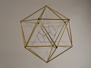
Figure 5a. Polarity of Icosahedron and Dodecahedron, brass and aluminum, 34x34x34 cm
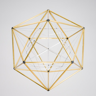
Figure 5b. Polarity of Icosahedron and Dodecahedron, brass and aluminum, 26x26x326 cm
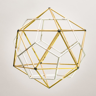
Figure 5c. Polarity of Icosahedron and Dodecahedron, brass and aluminum, 21x21x21 cm
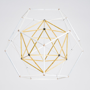
Figure 5d. Polarity of Icosahedron and Dodecahedron, brass and aluminum, 26x26x26 cm
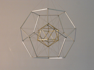
Figure 5e. Polarity of Icosahedron and Dodecahedron, brass and aluminum, 34x34x34 cm
|
6. The Polarity of the Tetrahedron
Figure 6 shows that the polar of a tetrahedron is indeed a Platonic solid, but it is just another tetrahedron. There is no sixth Platonic solid.
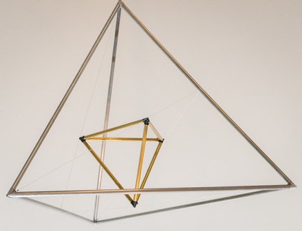
Figure 6. Polarity of Tetrahedron to Itself, bass and aluminum, 20x20x20 cm
7. Rotation Groups
The Group of Symmetries of an Object
The idea of symmetry has to do with the repeating of a pattern within a figure. We make the concept more precise by saying that a symmetry of an object is a rigid movement of the object to itself. If it moves a right-handed glove to a right-handed one, as does a rotation, then we say that it preserves orientation. If, on the other hand, it moves a right-handed glove to a left-handed one, as does a mirror reflection, then we say that it reverses orientation.
The set of all symmetries of an object has a structure to it. If one symmetry is followed by another, the result is a third symmetry, called the composition of the two. There is an identity symmetry, also called the trivial symmetry, which moves (we stretch the use of the word “move”) every point to itself. Each symmetry has an inverse symmetry (reverse the movement). Also, it satisfies an associative property, a(bc) = (ab)c. Thus, the set of symmetries with the operation of composition form what is called a group, a structure that is ubiquitous in modern mathematics. The theory of groups helps us understand the nature of symmetry and determine the possible types. Thus, the order that we intuitively experience in observing a symmetrical object expresses itself not only spatially, but also algebraically.
The Group of Rotations of an Object
We will confine our attention in this text to orientation-preserving symmetries. The composition of two of them is again orientation-preserving (the right-hand goes to a right-hand to a right-hand). So, all of the orientation-preserving symmetries of an object are themselves a group. It is a sub-group of the group of all symmetries. A remarkable theorem of Euler tells us that any orientation preserving symmetry of a finite object is just a rotation about some axis. In other words, if you pick up a ball, toss it around, and put it back down in the same place, then that same result could have been achieved by rotating the ball about a radial axis. A proof of this theorem is given in the Appendix. Therefore, the group of orientation-preserving symmetries of a finite object can be called the rotation group of the object.
The Order of an Axis and the Order of a Group
Figure 7a is a mobile with two models hanging in it. In one of the models there is a vertical black rod going through the top vertex and the bottom face. The tetrahedron has three edges at the top vertex and three edges on the bottom face. If the tetrahedron is rotated about that vertical black rod by 0°, 120°, or 240°, the whole tetrahedron returns to itself. Since there are three rotations about the vertical black rod that make a symmetry of the tetrahedron, we say that that axis of rotation has order 3. That model has altogether four black rods, each an axis of order 3. The other model in the mobile has black rods through the midpoints of opposite edges. Each of these is an axis of order 2, because the tetrahedron can be rotated about that axis by 0° or 180°. The 0° rotation is the trivial rotation. All of these rotations of the tetrahedron are enumerated in the first table below. The order of a group of rotations is the total number of rotations in it. The table shows the group of rotations of the tetrahedron to have order 12.
Figure 7b shows all of the axes of rotation of the octahedron and cube. Figure 7c does likewise for the icosahedron and dodecahedron. These rotations are all enumerated in the following tables.
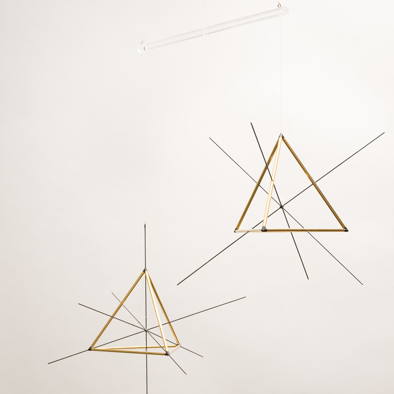
Figure 7a. Axes of the Tetrahedron mobile, brass & carbon fiber, 75x75x60 cm
|
Rotations of the Tetrahedron
Location of axis midpoint face center of edge & vertex order of axis 2 3 no. of non-trivial rotations 1 2 no. of axes 3 4 subtotal of non-trivial rot. 3 8 11 trivial rotation 1 total no. rotations 12 |
|
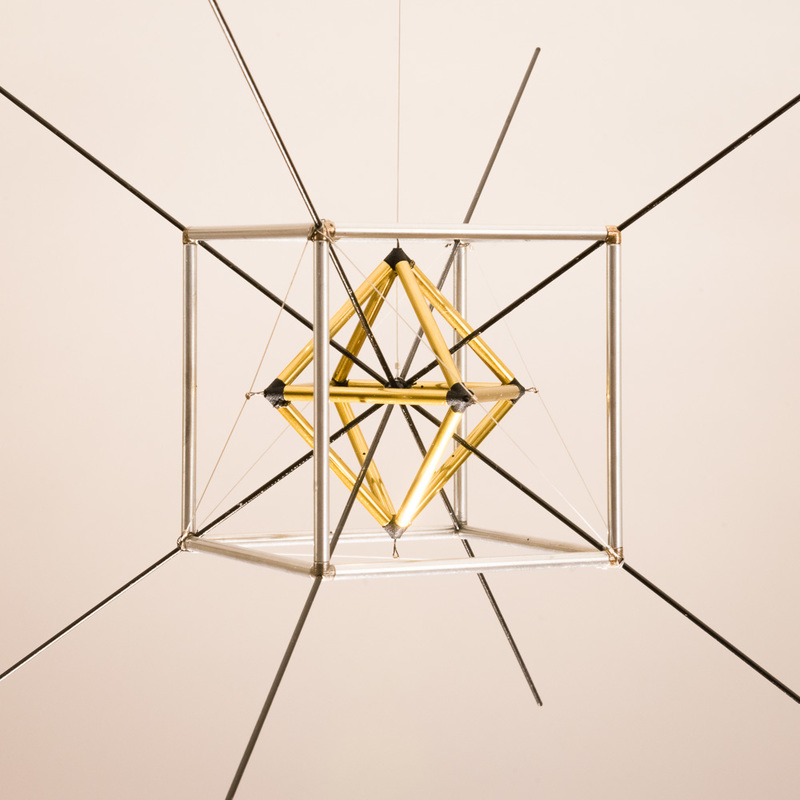
Figure 7b. Axes of the Cube and Octahedron, brass, aluminum, & carbon fiber. The three models are part of one mobile, 107x107x91 cm
|
|
Rotations of the Octahedron
Location on octahedron edge face vertex
Location on cube edge vertex face
order of axis 2 3 4
no. non-trivial rotations 1 2 3
no. axes 6 4 3
subtotal non-trivial rot. 6 8 9 23
trivial rotation 1
total no. rotations 24
Location on octahedron edge face vertex
Location on cube edge vertex face
order of axis 2 3 4
no. non-trivial rotations 1 2 3
no. axes 6 4 3
subtotal non-trivial rot. 6 8 9 23
trivial rotation 1
total no. rotations 24
|
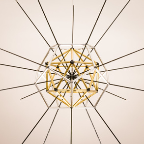
Figure 7c. Axes of the Icosahedron and Dodecahedron, brass, aluminum, & carbon fiber. The three models are part of one mobile, 107x107x91 cm
|
|
Rotations of the Icosahedron
Location on icosahedron edge face vertex
Location on dodecahedron edge vertex face
order of axis 2 3 5
no. non-trivial rotations 1 2 4
no. axes 15 10 6
subtotal non-trivial rot. 15 20 24 59
trivial rotation 1
total no. rotations 60
Location on icosahedron edge face vertex
Location on dodecahedron edge vertex face
order of axis 2 3 5
no. non-trivial rotations 1 2 4
no. axes 15 10 6
subtotal non-trivial rot. 15 20 24 59
trivial rotation 1
total no. rotations 60
Exercise 2: Identify which of the three models in Figure 7c belongs to each of the three columns in the above table. Also count the number of axes in each model to verify the counts given in the table.
Question 3: The tetrahedral, octahedral, and icosahedral groups have 12, 24, and 60 rotations, respectively, all multiples of 12. Why is that? Why does the octahedral group have exactly twice the order of the tetrahedral group and the icosahedral five times the order of the tetrahedral? Can we see this geometrically somehow?
Question 3: The tetrahedral, octahedral, and icosahedral groups have 12, 24, and 60 rotations, respectively, all multiples of 12. Why is that? Why does the octahedral group have exactly twice the order of the tetrahedral group and the icosahedral five times the order of the tetrahedral? Can we see this geometrically somehow?
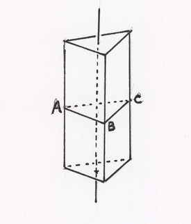
Reducible and Irreducible
This triangular prism has one vertical axis of order 3 and three horizontal axes of order 2. Every symmetry of the prism leaves the vertical axis invariant, i.e. it brings it back to itself, and leaves the horizontal triangle, ABC, invariant as well. Its symmetries are just combinations of symmetries of the one-dimensional vertical axis and the two dimensional horizontal triangle. The prism is a three-dimensional figure, but its symmetry is made up of symmetries of lower dimensional forms. We say that its group of rotations is reducible. If there is no one plane left invariant by all the rotations in a group, then the group of rotations is called irreducible. Its symmetry is truly three-dimensional. So, what are all the possible forms of three-dimensional symmetry? We have the following remarkable theorem:
Theorem: The groups of rotations of the Platonic solids are the only finite irreducible groups of rotations of 3-space.
A proof is given in the Appendix.
This means that any form with three-dimensional symmetry has the exact same group of rotations as one of the Platonic solids, i.e. its axes of rotation are identical to one of the ones shown in Figures 7a, 7b, or 7c. The ancient Greeks found the Platonic solids to be the only convex regular polyhedra. In modern times we find another way in which they are fundamental to the nature of space: They represent all possible finite three-dimensional symmetry.
Exercise 3: Look through the extensive art exhibition at this Bridges conference for sculptures that have irreducible symmetry – there are many – and identify their group of rotations: the tetrahedral, octahedral, or icosahedral.
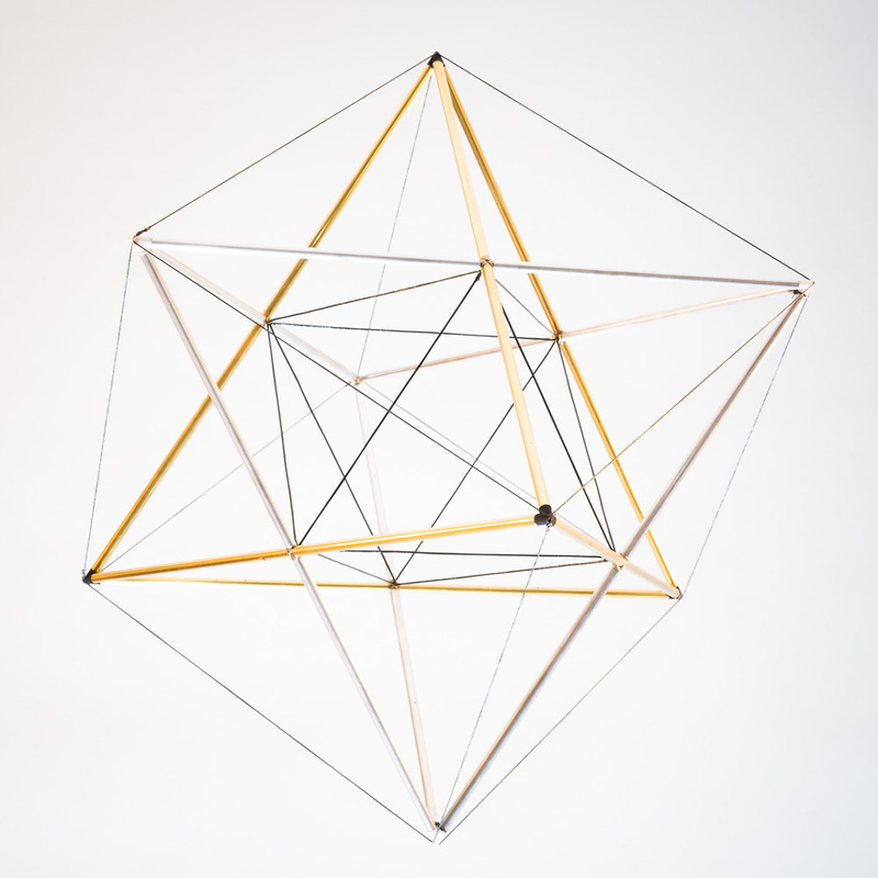
Figure 8a. Stella Octangula with Cube and Octahedron, brass and aluminum, 25x25x25 cm
|
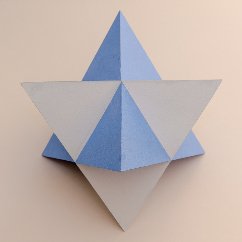
Figure 8b. Stella Octangula, cardboard, by Steve Morse
|
8. The Tetrahedron in Relation to the Cube and Octahedron
Figures 8a and 8b show two intersecting tetrahedra, which are polar to one another. Kepler called this the stella octangula. Figure 8a shows the two tetrahedra in metal, and also shows in black string their intersection, which is an octahedron, and the enclosing form, which is a cube. The tetrahedra share vertices with the cube and share face planes with the octahedron. In both 8a and 8b, the whole figure is polar to itself.
Subgroups and Cosets
Now, let’s consider the rotations of the brass tetrahedron. The tetrahedron’s order 3 axes through its vertices are also axes of order 3 of the cube through its vertices, and the tetrahedron’s axes of order 2 through its edges are also axes of the cube of order 4 through face centers. So, every rotation of the tetrahedron is also a rotation of the cube. A group that is contained within a larger group is called a subgroup. So, we see that the tetrahedral rotation group is a subgroup of the rotation group of the cube. The cube has 24 rotations, moving the cube to itself; 12 of those also move the brass tetrahedron to itself. What do the other 12 rotations of the cube do to the tetrahedron? It has to move to another tetrahedron. The brass tetrahedron must be moved to the aluminum one in Figure 8a (or the blue to the gray in Figure 8b). The group of all 24 rotations of the cube is thus partitioned into two subsets of 12 rotations each; those in one subset move the brass tetrahedron to itself; those in the other subset move it to the aluminum one. These two subsets are called cosets, and the fact that the tetrahedral subgroup partitions the group of the cube into cosets of equal size is a characteristic of subgroups, as we will explain more fully in the next section.
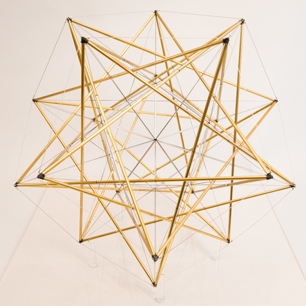
Figure 9a. Five Tetrahedra in Tensegrity, brass, 40x40x40 cm
|
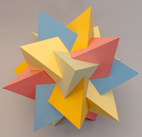
Figure 9b. Compound of Five Tetrahedra, cardboard, by steve Morse
|
9. The Tetrahedron in Relation to the Dodecahedron and Icosahedron
Figures 9a and 9b each show a compound of five tetrahedra. Figure 9a also shows the encasing dodecahedron (in steel wire), and the icosahedron (in aluminum tubes), which is the intersection of the five tetrahedra. For each of the tetrahedra, all of their vertices lie on vertices of the dodecahedron and all their faces share face planes with the icosahedron.
Subgroups and Cosets Again
In section 8 above, we saw that the tetrahedral group is a subgroup of the octahedral group. Here in Figure 9a, we see that the tetrahedral group is a subgroup of the icosahedral group. All the rotations of any one tetrahedron in the figure are also rotations of the encasing dodecahedron (and also the enclosed icosahedron). Now in figure 9b consider the red tetrahedron. Let
R1, R2, ..., R12
be the 12 rotations of the dodecahedron which move the red tetrahedron to itself. How many rotations of the dodecahedron move the red tetrahedron to, say, the blue one? Well, if S is any one rotation moving the red tetrahedron to the blue one, then
SR1, SR2, ..., SR12
will all move the red tetrahedron to the blue one, (SR means first do R, taking red to red and then do S, taking it to blue).
Moreover, these are the only ones taking the red tetrahedron to the blue one. In fact, if T takes the red to the blue, then S-1T takes red to blue and back to red; hence S-1T = Rn for some n; hence T = SRn.
This shows that there are precisely 12 rotations that take the red tetrahedron to the blue one. The set of these 12 is called a coset of the tetrahedral subgroup. We have shown that it has the same number of elements as the tetrahedral subgroup. In the same way, one sees that there is a coset of 12 rotations, moving the red tetrahedron to each of the other three tetrahedra as well. Altogether, there are five cosets of 12 rotations each, making up the full group of 60 rotations of the dodecahedron. Now we understand why the order of the tetrahedral group divides evenly into the order of the dodecahedral group. We have answered question 3 above. Moreover, with a very similar argument, one proves a theorem of Lagrange, which asserts that the order of any finite group is divisible by the order of any subgroup.
Mirror Symmetry
Most of the figures in this textbook have mirror symmetry. They are identical to their mirror image. However, this compound of five tetrahedra is different from its mirror image. Looking down an axis of order five toward the center, one sees a right-handed screw movement. The mirror image is left-handed.
Further Group Theory
It’s much easier for a student to grasp a new concept when they have a picture to illustrate it. Other topics, arising in a further study of group theory, are well illustrated by Figures 8a, 8b, 9a and 9b. We mention here a couple of examples for the reader familiar with a little group theory.
The group of rotations of the icosahedron is the alternating group on 5 objects; this is most easily proved by observing that any such rotation gives an even permutation of the five tetrahedra in Figures 9a and 9b, and noting that the rotation group has the same order, 60, as the alternating group on five objects.
The notion of conjugate subgroups is nicely illustrated here. Each of the five tetrahedra in Figures 9a, 9b has a group of rotations that is a subgroup of order twelve of the icosahedral group. These five subgroups are all conjugate to one another. In fact, if B is the subgroup of rotations, leaving the blue tetrahedron invariant, and R is a rotation moving the blue tetrahedron to the red one, then R B R is the subgroup, leaving the red tetrahedron invariant, and so forth. In contrast, in Figures 8a, 8b the two tetrahedra have the same subgroup of rotations, which has index 2, and illustrates the notion of a normal subgroup.
The notion of conjugate subgroups is nicely illustrated here. Each of the five tetrahedra in Figures 9a, 9b has a group of rotations that is a subgroup of order twelve of the icosahedral group. These five subgroups are all conjugate to one another. In fact, if B is the subgroup of rotations, leaving the blue tetrahedron invariant, and R is a rotation moving the blue tetrahedron to the red one, then R B R-1 is the subgroup, leaving the red tetrahedron invariant, and so forth. In contrast, in Figures 8a, 8b the two tetrahedra have the same subgroup of rotations, which has index 2, and illustrates the notion of a normal subgroup.
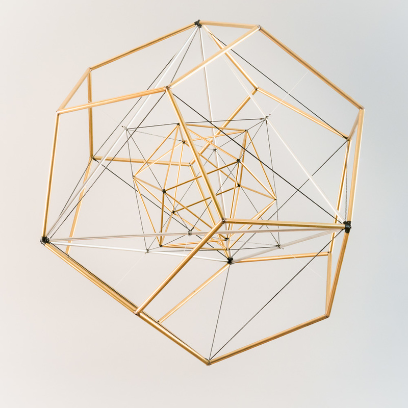
Figure 10. All Together, brass and aluminum, 40x40x40 cm
10. All Five Platonic Solids Together
In general, the tetrahedron is the simplest of all possible polyhedra. Any other polyhedron has more vertices, more faces, and more edges. Moreover, among the Platonic solids, the regular tetrahedron plays a very special role. We saw in Sections 8 and 9 above that the regular tetrahedron can be aligned with any other Platonic solid in such a way that all of its rotations are also rotations of the other one as well, i.e. it is a subgroup. Hence, one can line up any two Platonic solids so that four axes of order 3 coincide. Then, by adjusting the relative sizes of the two, one finds many interesting geometric relationships. Most of the models in this textbook are obtained in this way.
In Figure 10 we see all five Platonic solids together in relation to one another.
The tetrahedron, octahedron, and icosahedron, the ones with triangular faces, all share four faces with each other.
The tetrahedron, cube, and dodecahedron, the ones with triangular vertices, all share four vertices with each other.
The figure is self-dual.
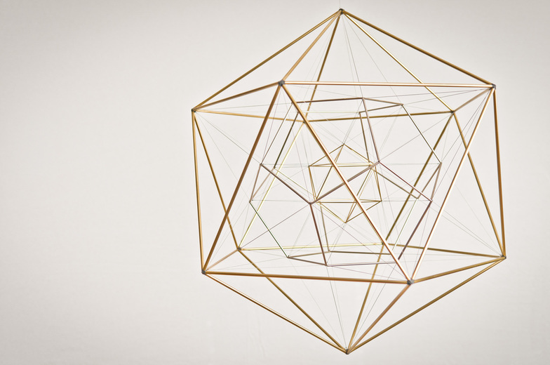
Figure 11a. As Above So Below I, brass, chrome, 50x50x50 cm
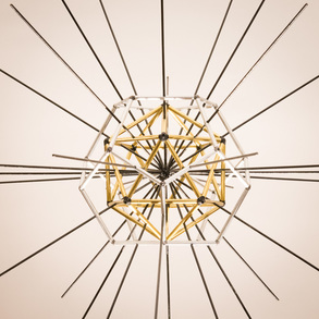
11. Nesting in Geometric Progression
A geometric progression is a sequence of numbers that grows, as it progresses, by multiplying each term by the same fixed number, to get the next term. The fixed number is called the common ratio.
Revisiting Figures 5a Through 5e
Look again at Figures 5a through 5e. They show a geometric progression. We measure diameters from the midpoint of an edge to the midpoint of the opposite edge, and let the sphere of polarity (see Section 3 above) have diameter 1.
Let φ = golden mean = (1 + √5)/2 ≈ 1.618
In going from left to right, Figure 5a to 5e,
dodecahedron diameter = 1/φ, 1/√φ, 1, √φ, φ
icosahedron diameter = φ, √φ, 1, 1/√φ, 1/φ
(dodecahedron diam)/(icosahedron diam) = 1/φ^2, 1/φ, 1, φ, φ^2
Thus the dodecahedra form a geometric progression, getting larger by a factor of √φ with each step to the right, while the icosahedra form a geometric progression, getting smaller with each step to the right by a factor of 1/√φ. The ratio of the two diameters thereby grows by a factor of φ.
The Icosahedron and Dodecahedron in Geometric Progression
Now consider Figure 11a. Can you see that it contains both Figures 5b and 5e? The geometric progression has been combined into one figure. The ratio of the large icosahedron on the outside to the little one in the center is φ^3.
Visualization 3: Imagine Figure 11a continuing inward. The small icosahedron could have another dodecahedron suspended inside it, and so on, continuing inward indefinitely far. Also, picture the figure continuing outward. The edges of the outside icosahedron could be extended to points, which when joined up, would form a very large dodecahedron. That in turn could be extended outward to another icosahedron and so on, indefinitely far.
Question 4: What would the polar of Figure 11a look like?
Question 5: Since in Figure 11a the ratio of the large icosahedron to the small one is φ^3, there must be two more icosahedra between them with ratios of φ and φ^2 to the small one. What would that look like? How could they be suspended?
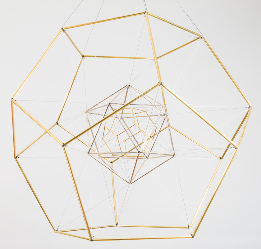
Figure 11b. As Above So Below II, brass and chrome, 50x50x50 cm
The Dodecahedron and Icosahedron in Geometric Progression
Now consider Figure 11b. It also contains both Figures 5b and 5e, but in the opposite order from Figure 11a. This is the polar of Figure 11a, which answers question 4 above.
Visualization 4: Imagine Figure 11b continuing inward indefinitely far and also outward indefinitely far, similarly to Visualization 3 above.
Question 6: In Figure 11b, the ratio of the large dodecahedron to the small one is φ^3. So, there must be two more dodecahedra in between them with ratios of φ and φ^2 to the small one. What would that look like? How could they be suspended?
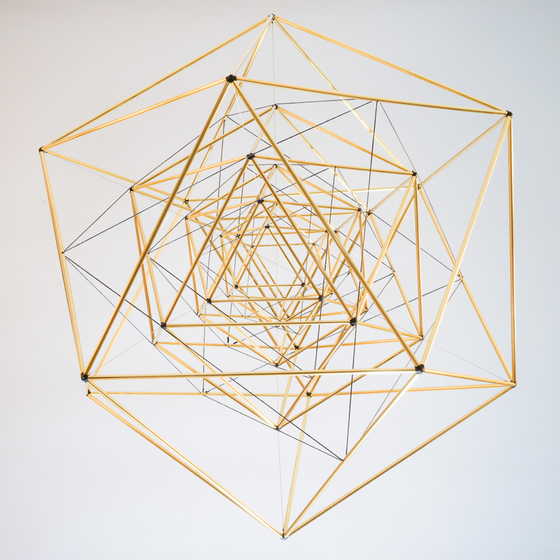
Figure 11c. Icosahedron and Octahedron in Geometric Progression, brass, 50x50x50 cm
The Icosahedron and Octahedron in Geometric Progression
Figure 11c is a nested sequence of icosahedra (brass tubes) and octahedra (black string). Each octahedron is inscribed in an icosahedron with each of its vertices on the midpoint of an edge of the icosahedron. The octahedron then has inscribed within it the next smaller icosahedron. Each of the 12 vertices of that icosahedron lies on one of the 12 edges of the octahedron at the golden mean division point of the edge. The ratio of the icosahedron to the next smaller one is the golden mean, φ. Figure 11c answers question 5, above.
Question 7: What would the polar of Figure 11c look like?
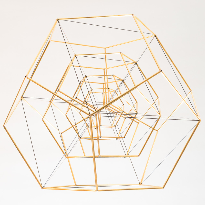
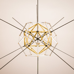
Figure 11d. Dodecahedron and Cube in Geometric Progression, brass, 50x50x50 cm
The Dodecahedron and Cube in Geometric Progression
Figure 11d is a nested sequence of dodecahedra and cubes. Each cube is inscribed in a dodecahedron with each of the cube’s 12 edges on one of the 12 faces of the dodecahedron. The cube then has inscribed within it a smaller dodecahedron with each face of the cube on an edge of the dodecahedron. The ratio of the dodecahedron to the next smaller one is the golden mean, φ.
Figure 11d answers questions 6 and 7, above. Also, a photo of it is on the cover of the Bridges 2015 art exhibition catalogue.
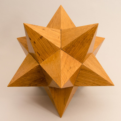
Figure 12a. Small Stellated Dodecahedron, wood, by Bob Rollings
|
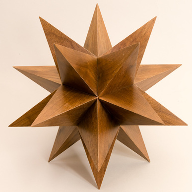
Figure 12b. Great Stellated Dodecahedron, wood, by Bob Rollings
|
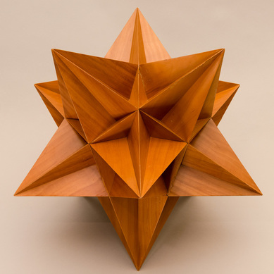
Figure 12c. Great Icosahedron, wood, by Bob Rollings
|
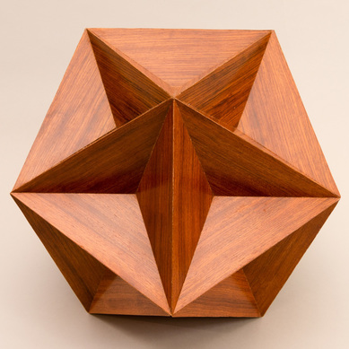
Figure 12d. Great Dodecahedron, wood, by Bob Rollings
|
12. The Kepler-Poinsot Polyhedra
The five Platonic solids are the only convex regular polyhedra. However, if we drop the convexity requirement, and ask for non-convex regular polyhedra, then four more appear. They are called the Kepler-Poinsot polyhedra. A proof that these are the only four can be found in Regular Polytopes, H. S. M. Coxeter, Dover, 1973. The faces will be regular polygons, but they may be star-shaped, and likewise a truncated vertex may appear as a star-shaped polygon. These four polyhedra are shown in wood in Figures 12a, b, c, and d.
Exercise 4: Look at Figure 13, hanging above Figures 12a, b, c, and d. It is the same as Figure 11a. Each of the four Kepler-Poinsot polyhedra can be found within the one model, Figure 13. Look for them. With some effort and persistence, you can find them all.
Acknowledgements
Georg Unger (1909 – 1999), of Dornach, Switzerland, suggested to me many decades ago that the Platonic solids were figures worthy of contemplation. Bob Rollings and Steve Morse contributed some wonderful models to the exhibit. I thank the Board of the Bridges organization and especially George Hart for encouraging me in this project. George and also Carlo Sequin helped me get started with 3D printing. The joints were 3D printed by Shapeways. Metro Plating in Kensington, MD carefully and skillfully did all of the plating and lacquering of the pieces. Jason Pogacnik took the beautiful photographs in the Proceedings article. James Sullivan is generously contributing his professional skills to create a video about this 3D-Textbook. Iris Levin has kindly agreed to build a website for the exhibit. My wife, Judy Levin, with her artistic sensibility, has given enormous support in this project.
Georg Unger (1909 – 1999), of Dornach, Switzerland, suggested to me many decades ago that the Platonic solids were figures worthy of contemplation. Bob Rollings and Steve Morse contributed some wonderful models to the exhibit. I thank the Board of the Bridges organization and especially George Hart for encouraging me in this project. George and also Carlo Sequin helped me get started with 3D printing. The joints were 3D printed by Shapeways. Metro Plating in Kensington, MD carefully and skillfully did all of the plating and lacquering of the pieces. Jason Pogacnik took the beautiful photographs in the Proceedings article. James Sullivan is generously contributing his professional skills to create a video about this 3D-Textbook. Iris Levin has kindly agreed to build a website for the exhibit. My wife, Judy Levin, with her artistic sensibility, has given enormous support in this project.
